Wednesday, April 3, 2013
2009 BMW 1 Series Owner’s Manual
Download: 2009 BMW 1-Series Owner’s Manual

Audi TT DIY B5 A4 Pre 99 5 BPV DV Install
I changed my BPV / DV (bypass valve / diverter valve) today (710N), so I snapped some pics and thought Id post in case anyone was interested.
I have a 1997, so the BPV is NOT in the same spot as most A4s. Its located higher up, and you really cant get to it from below. So, there is no need to jack up the car for this.
Tools needed:
1. Flathead and Phillips screwdriver.
2. Size 30 Torx socket attachment (for the headlight removal).
3. Small Hands.
Optional:
- Extra Vacuum hose. Size 3.5mm or 5/32".
- Little clamps for vac hose that you replace (can get at www.ecstuning.com). Or just use zip ties.
STEP 1: Remove airbox cover pieces.
Just pop off the plastic covers over the air box (you DO NOT have to remove the airbox, just the covers). The cover pops off, and the flex snorkel too. The little snorkel piece in the front has two screws holding it in.
STEP 2: Remove Headlight.
Theres three torx screws holding in the headlight. First pop out the sidemarker (this if for those with 2-piece). Then youll see the side screw. The other two are right on top of the headlight.

You can then pull out the light, and can easily pop off the wiring connector (just push the little silver clip down, and the plug comes out) then you can completely remove the headlight housing.
Heres what you see when you look in:

STEP 3: Loosen clamps to move the hose from the air box out of the way.

Just loosen the two clamps (number 1 and 2 in the pic) enough to you can move that big flex hose enough to get better access to the BPV clamps. Number 3 is optional if you think it will give you better access. That is the connector to the N75 valve. Theres a silver clip you can push in and pop off that connector. Just be careful with it.
Heres the hoses removed:

STEP 4: Get to the BPV!
Now when you hold that big hose out of the way, you should able to get a decent view of the BPV (which is behind the fan).

Theres two flathead screw clamps holding the BPV on to each hose attached to it. One of them you cannot get to yet. The first is a bit tricky. I put one arm in through the headlight hole to hold the BPV and clamp at an angle where I could get the screwdriver on it from above. Its a bit frustrating but very do-able. After you loosen it enough, pull that end of the BPV out of that hose. The other end (towards the IC piping) of the BPV is still attached. You should now be able to weasel your way over to that clamp to loosen.
Now the BPV is basically free. The only thing still attached should be the vacuum hose going to the manifold.

Remove that vac hose. If the hose is old/brittle then you should replace it now. The hose size is 5/32 inches (available at Autozone), its also the same as the 3.5mm ID hose.
Now hook up your new BPV to the vac hose, and put it all back together and check for leaks via your boost gauge. If you dont have a boost gauge, stop modding your car and get one before you bother modding!

search terms: changing BPV bypass valve DV diverter valve 710N 97 how to change BPV write-up install installing installation instructions puting in new BPV
Audi A3 Euro Rubber Floor Mats
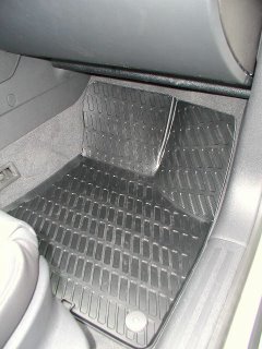
Some sort of all-weather mats are an absolute necessity. Carpet mats are magnets for grit, salt stains, etc., and cant be hosed off and put back in right away. I looked at all the options:
- Hexomat, like my cargo liner
- WeatherTech (had them in a previous car, liked them a lot)
- Audi Monster mats, which are similar to the WeatherTech design but have A3 printed on them
- Audi Euro Rubber mats
I ordered them from AutoWebAccessories, which sells genuine accessories at a discount. They were backordered nationwide, but I got mine as soon as they were available in the country. They work great, and I highly recommend them.
One problem was that the snaps were so tight that they could have ripped the fastener out of the carpet. Scraping the inside of the snap on the mat with a knife made them snap on well, but not insanely tight. They give the interior a neat, sporty look. In the photos below they look like they contrast a lot with the carpet, but thats mostly due to the camera flash. In reality, the black mats are very subtle against the black carpet:


Coding the Control Module for the Audi TT Coupe
The Audi TT comes with several pre-programmed functions in the central locking control module that can be accessed by using the VAG 1551/1552/5051 tools (available to Audi dealers), or PC emulation programs such as the old VWTool, Baums VDS-PRO, or Vag-Com from Ross-Tech. These tools can be used to check your cars diagnostic codes, but they also allow you to make certain modifications to the default programming.
Listed below are several of the codes that will modify the central locking control module in the Audi A4 to access some of the hidden features available on these cars. Please note that Audi of America does not officially recognize that these codes exist and some dealers are unwilling to make modifications to the factory control module coding. You assume all responsiblity and liability associated with these modifications.
To make modifications to the factory settings, numbers are added to and subtracted from the default setting code numbers. Below is a table thatb lists several of these functions and the programming required to access these functions. The value is the number added to or taken away from the default programming.
Please note that these codes are for cars in the North American market.
| Function | Value |
| Add Window Up/Sunroof close, and Window Down with remote.* | +64 |
| Add 1 touch unlock of both doors | -04 |
| Remove horn honk when arming | -1024 |
| Auto lock/unlock of doors (Doors lock at 15 mph and unlock when key is removed) | +32 |
The coding depends on which radio is installed in your car from the factory. The table below shows the total coding value for certain functionality packages that I have experimented with.
| Functions | Coding with Concert Radio |
| (Factory Default)Safety Central Locking**Horn sounds when armingLights flash when arming | 15884 |
| Window control with remote1 touch unlock of both doorsNo horn sound when armingLights flash when arming | 14920 |
| Window control with remote1 touch unlock of both doorsHorn sounds when armingLights flash when arming | 15948 |
| Window control with remoteSafety Central Locking**Horn sounds when armingLights flash when arming | 15952 |
| Window control with remoteSafety Central Locking**No horn when armingLights flash when arming | 14924 |
| Window control with remote1 touch unlock of both doorsNo horn sound when armingLights flash when armingAutomatic door lock/unlock | 14952 |
| Window control with remote1 touch unlock of both doorsHorn sounds when armingLights flash when armingAutomatic door lock/unlock | 15976 |
| Window control with remoteSafety Central Locking**Horn sounds when armingLights flash when armingAutomatic door lock/unlock | 15980 |
| Window control with remoteSafety Central Locking**No horn when armingLights flash when armingAutomatic door lock/unlock | 14956 |
**Safety Central Locking - 1 press of unlock opens drivers door, 2nd press opens passenger door.
Coding Instructions (emulation software)
1. Plug your your computer with emulation software loaded into the Data Link Connector (OBDII port) in your car. This Data Link Connector is located on the drivers side, below the dash, close to the door. Start software. You should see a list of the different modules available.

2. Select your control module that you want to recode. In this case, its the Central Locking control module. In a direct entry address system (VAG1551/1552) enter address word 35 (Central Locking).
3. Your screen should show the current coding of your control module listed as Software Coding.

4. You want to Recode the control module. You dont need to Login to do this. Select Recode.
5. Enter the coding that you want from the above list, depending on the features you desire, make sure your numbers are correct, select Do It or press enter.

6. Your new features should be available immediately.
Coding Instructions (VAG 1551/1552)
1. Plug your your VAG tool into the Data Link Connector (OBDII port) in your car.
2. Rapid data transfer. Insert address word XX should be displayed. Press buttons 3 and 5 to insert Central Locking address word 35. Press Q button to confirm the input.
3. Rapid data transfer. Select function XX should be displayed. Press buttons 0 and 7 to select Code Control Module function 07. Press Q to confirm the input.
4. Code Control Module. Enter code number XXXXX (0-32000) should be displayed. Enter control module coding number from above table using the keypad. Press Q to confirm the input.
5. Display will show control module identification and that the coding has been entered. Press the arrow button.
6. Rapid data transfer. Select function XX should be displayed. Press buttons 0 and 6 to select End Output function 06. Press Q to confirm the input.
7. Disconnect your VAG tool from the Data Link Connector.
Please note: Beware when attempting to code a 98 or newer VW/Audi with an aftermarket radio. The adapter harness that is supplied by the aftermarket ties the "K" line to VBatt. Any service tool or computer that is used on the vehicle may be damaged unless it has been properly fused.
Since these items are not coded from the factory to be readily accessible, and Audi of America does not officially recognize these modified codes, you assume all the risks involved with re-coding your central locking control module. Audi TSB 98-07, which can be found at tech.vw.com covers some changes to the central locking control module that Audi of America does recognize. Please be aware that dealers may charge you for this service, or they may not be willing to perform this service. Some dealers may be unfamiliar with the fact that you can re-code the central locking control module, or they may re-code the central locking control module to factory settings. It would be a good idea to keep a copy of this document with the car in case any questions arise.
When forwarding and making copies of this document, please keep it intact.
Tuesday, April 2, 2013
2011 Audi A3 Owners Manual brochures
Download: 2011 Audi A3 Owners Manual brochures
2010 Subaru Foresterd Owner Manual
Before you operate your vehicle, carefully read this manual. To protect yourself and extend the service life of your vehicle, follow the instructions in this manual. Failure to observe these instructions may result in serious injury and damage to your vehicle.
Table of content 2010 Subaru Forester Owners Manual
- Seat, seatbelt and SRS airbags
- Keys and doors
- Instruments and controls
- Climate control
- Audio
- Interior equipment
- Starting and operating
- Driving tips
- In case of emergency
- Appearance care
- Maintenance and service
- Specifications
- Consumer information and Reporting safety defects
- Index
Audi A3 Nav RNS E and Bluetooth Retrofit single DIN to double DIN conversion
Anyway, I figured that since I was already doing that upgrade, I might as well throw in the OEM Bluetooth module and kill two birds with one stone (as the saying goes...).
It always bothered me that I hadnt ordered these two options straight from the factory. So, I took it upon myself to ease my irritation

My camera ended up dying after taking snaps of the parts, so I didnt want to wait until it was charged to do the installation. So, the pics are of the parts, and finished results. I will describe in detail how to do the full install.
1) Full list of needed parts - pictures and part numbers:
NOTE: THESE ARE THE ONLY PARTS YOU NEED - dont waste you $ getting other parts that have been posted as necessary:
a) Radio removal keys
- I got these from eBay - $10 including shipping.

b) Double-DIN cage
PART NO: 8P0 858 005 A
CAN $95.00

c) Blanks (non-functional buttons)
PART NOS:
LEFT: 8P0 941 515 C 5PR
RIGHT: 8P0 941 516 C 5PR
CAN $10.73 each
ESP Switch:
PART NO: 8P0 927 134 C 5PR
CAN$ 35.00
*YOU DO NOT NEED A NEW HAZARD LIGHT SWITCH - Single-DIN Hazard light fits the same, even though part number is different*
** NONE OF THE OTHER BUTTONS WILL WORK - Single-DIN button, including ESP switch, are all larger**

d) Card Shelf:
PART NO: 8P0 941 561 E 5PR
CAN $85.00 (What a joke... 
*AGAIN, Single-DIN card shelf is too big for the double-DIN cage*
e) Center trim (Goes around switches - again, double-DIN specific):
PART NO: 8P0 863 321 C 6PS
CAN $52.65
e1) THIS IS FOR US CARS ONLY:
Passenger Airbag Warning Light for double-DIN
PART NO: 8P0 919 234 A 5PR
e2) FOR THOSE WITH TPMS OR WANTING TO RETROFIT TPMS:
TPMS switch for double-DIN
PART NO: 8P0 927 121 A 5PR
f) RNS-E Unit
PART NO: 8P0 035 192
**NEW UNITS HAVE A LETTER AT THE END OF THE PART NO: B, C, F, and G**
Bought off eBay for US$900


g) RNS-E wiring harness - make sure to get the adapter to work with non-BOSE, w/out telephone (if no BT), w/ CD Changer
**Use this harness only if youre not retrofitting the Bluetooth module at the same time - that requires a different harness**
Can be had on eBay, or NavParts.com or Euro-Parts.us. RNS-E sellers should include this harness though.

h) GPS antenna and Radio antenna adapter
*These parts should also be included in your RNS-E purchase

i) Other needed things:
Painters tape (for protection)
Double-sided tape (optional)
Dremel +
flexible add-on (optional)
Soft cloth polishing dremel tool
Cutting tool
Tool kit - Hex nuts, torx bits, strong hands!


Bluetooth Parts - optional (not needed for RNS-E install)
*I purchased all these parts from Lee at NSX JR. Hes a great guy, helped me out with everything from the install to coding both my RNS-E and BT unit with VagCom
a) Bluetooth Module; RNS-E wiring harness (with mic and BT wires already built in)
b) BT antenna; BT mic


Now, if you have all these parts in hand, youre ready for the install.
INSTALLATION:
Unfortunately, like I said, I dont have pics from the install itself. Its just a matter of unscrewing and removal and replacing.
If youre worried about scratching up your dash, put a towel across your handles, and use painters tape on the outer trim of the centre console.
I didnt do either since I was exceedingly careful... but use your own judgement.
1) Remove Concert II radio
Using 2 radio removal keys, remove the old radio.
*Insert the keys with the hooks facing inward* Once the keys pop in, you cant remove them until the radio is out.
Once removed, disconnect the adapters. Dont worry about not knowing what goes where after - its a simple puzzle. They are colour coded and are size dependant as well.
2) Once the radio is removed, pull off the upper trim piece. Itll pop out easily.
3) Remove blank switches, ESP switch, Hazard ligh switch, and Card holder.
The blanks pop out easily.
The ESP and Hazard switches need to be pulled out and unplugged - again dont worry about confusing them later - colour coded white and black.
The Card holder requires a fine tool to push down on small clips on the upper right and left side. (Easily seen with the drawer open).
4) Remove the climate control unit.
Itll pull out easily with the rest gone. Unhook all the cables - again colour coded and size dependant for later.
Now it gets fun.
5) Removal of ash tray.
Open the ashtray. Hook your fingers underneath where the ashtray meets the shift boot. Lift up firmly. The shift boot trim should pop up. There are two clips in the front and two in the back. Pull the boot up all the way over the gear shift (for 6MT) and put the car in 4th or 6th to get the stick out of the way.
6) Remove glove box and cover underneath steering wheel.
This is a simple process of removing bolts. There are many.
Under steering wheel:
a) Push light switch in, and twist to the right. It should pop out. Disconnect the two connections, and put switch away for later.
b) Remove fuse box panel cover.
c) Unscrew all the bolts underneath the fuse panel. Its obvious which ones are holding the lower dash on.
d) There are two bolts in the foot well. One on the right and one on the left. Unscrew both of those and the lower dash should come off.
e) The top will tilt down. With the top part down, pull outward and the rest of it should come off.
Glove Box:
a) Remove side panel
b) Open glove box and remove everything.
c) Unscrew all bolts - 3 or 4 on side by panel, another 6 or so found after opening the glove box.
d) After all the bolts are removed, the glove box will fall downward. Unhook the pass. airbag connection, the CD changer cable, and the in-box light cable.
7) Remove center console handles.
In the picture below, see the four circles in the shift boot area. Those need to be undone.
On the underside of the handles, in the middle, is a hole reaching to a HEX bolt. From memory, I think it was an 8mm bolt (could be 6mm...). Those two bolts need to be undone.

8) Unscrew the single-DIN cage
Where the red circles are, are torx screws. Unscrew all of them and another two screws on the side (glove box and driver foot well lower dash) and this should completely loosen the single-DIN. Loosening all these screws will also allow the handle bars to completely come off.


9) Remove the single-DIN cage
This sounds easier than it is. Its not meant to come out this way, but it will come. Pull out and twist down to the right. That worked for me.
**At this point, I had everything out. The ashtray and the "storage" area behind it were out. The entire dash had been taken out.**
Alright, very nice. The removing aspect of the job is done.... now its time for the good stuff. Installing.
10) Install the double-DIN cage
Again, sounds easier than it is. Just keep working it, and it will eventually go in. This is the part when I started sweating - taping the area would have been a great idea, but I managed not to scratch anything.
11) Line up the RNS-E unit in the cage.
Once the double-DIN cage is in, screw in the torx screws, but dont tighten.
12) Slide in the RNS-E unit, but not all the way in. Dont re-attach the cables.
This is check to make sure that the Nav+ will sit straight. If its straight, remove the RNS-E and then go hard with the torx screws.
13) Once all the torx screws have been tightened, install the RNS-E unit.
Attach the new cable harness, GPS antenna, Radio antenna, and push the unit all the way until it clicks.
14) Install the blanks, the two switches, and the new card tray.
15) Install the trim surround.
Now the sensitive part... cutting the climate control unit.
I didnt feel like shelling out $1,000 to buy a double-DIN climate control. So, I used a Dremel to shave down the sides so that it would fit.
16) Make a template of the shape of the new climate control.
I took a piece of cardboard and kept cutting it until it fit into the climate control area (on the bottom) like the actual unit would.
Once I had the exact shape, I centered it on my climate control and cut two rectangles for the knobs.
With the template centered on the climate unit, I traced the outline on it as the marks for cutting.
17) Using a dremel, shave down the sides of the climate control unit.
Take your time with this... keep shaving and testing, shaving and testing.
18) Once the fit is perfect, using a soft cloth polisher, buff the sides of the unit so that its smooth and not jagged from the sanding.
Hardest part is over!
19) Attach all the cables to climate control unit.
20) Wire your GPS antenna to a good location. I wired mine to the driver side fuse box. I get 4-8 satellites there all the time.
A lot of people have wired their antennas up in the instrument cluster.
Its magnetic so itll attach just about anywhere.
If youre really bold, you can get a FAKRA extension and wire it up to the existing sharkfin antenna on the roof... totally not necessary though.
21) Do not turn on car yet! If this is the end of the install, make sure you reinstall all the cables - light switch, pass. airbag, cd changer etc. or youll get a bunch of vag-com codes.
22) Put everything back together. Power on car. Hopefully everything should work - normal satellite reception is > 3.
23) For the ashtray area, I ended up doing a little bit of crude modifying. Since the double-DIN sits so much lower than the single-DIN, the storage area behind the ashtray is essentially eliminated. I didnt want to get a new bezel and trim that would be stuck in a hole Id never see.
After removing the existing storage area trim, youll see four tabs at the back. The two in the middle dont line up with the double-DIN.
I snapped them off.
The result... the same flooring of the storage area behind the ashtray, and more $$ in my pocket.
24) ADMIRE YOUR HANDYWORK!! 
25) Get your Vag Com cable out to do the necessary coding. If you dont have one, your dealer should be able to do the necessary coding for you.
----------------------------------------------
FOR BLUETOOTH RETROFIT, READ ON
1) I installed the module in my glovebox.
2) Run mic wire to preferred location.
I ran the mic wire up the passenger side A-pillar, across the headliner, and pulled it out in the overhead light console.
The mic now sits in the light console where those vents are, hidden from view. I get perfect voice reception with it up there.
3) Re-install everything.
4) Vag Com coding changes.
--------------------------------------------------------
Vag Com coding:
1) Select 19 - CAN gateway” and go into the Long Coding helper
Check on Byte 03, bit 7 (for telephone) - IF APPLICABLE, Bluetooth only
Check on Byte 03, bit 3 (for navigation)
2) Select 16 - Steering wheel: current coding 02022, new coding 04022
3) Select 37 - Navigation: current coding 0209217, new coding 0205617
4) Select 77 - telephone: current coding 0000000, new coding 0011477 - BLUETOOTH ONLY
**NOTE:
1) Since 6MT sports dont have DIS (in dash display), well always get an instrument cluster fault code. Theres no way to get rid of that fault.
2) Since there is no diversity antenna, all will get a "ZF Antenna" fault code in RNS-E (Select 77).
For example:
Steering Wheel:
1 Fault Found:
01317 - Control Module in Instrument Cluster (J285)
004 - No Signal/Communication
Nav:
2 Faults Found:
00858 - Connection; Radio ZF Output to Antenna Amplifier
011 - Open Circuit
01317 - Control Module in Instrument Cluster (J285)
008 - Implausible Signal
Radio:
2 Faults Found:
00858 - Connection; Radio ZF Output to Antenna Amplifier
011 - Open Circuit
01317 - Control Module in Instrument Cluster (J285)
008 - Implausible Signal
---------------------------------------------------------------------------
Well, that should do it, for this DIY.
BEFORE:

And some pics of the end result:
AFTER:


Oh, and whats this? Engineering Mode... very cool, if youre into a little bit more technical info: Location, Altitude, Road Speed...


EDITED TO INCLUDE PART NUMBERS FOR
1) Double-DIN Passenger Airbag Warning Light - for US A3s
2) Double-DIN TPMS Switch