Tuesday, April 2, 2013
Audi A4 B5 Remote programming with VAG
Have you received a new remote that you want to program to your car but find out that THIS (http://www.ross-tech.com/vag-com/car...-matching.html) didnt help you out much?
Remote Matching
For this procedure, you must have
1) VAG COM
2) A laser cut key (just one is "needed")
3) Up to 4 compatable remotes to program
Procedure for matching remote controls to most VW & Audi vehicles:
Under "Select Control Module"
"Select"
"46 - Cent. Conv." or "35 - Cent. Locking" (depending on year and make/model)
"Adaptation - 10"
First enter channel "00" as this will set all settings back to factory.
Enter channel "01" (Again "21 depending on make/model).
"Read"
This is supposed to display the number of currently stored remotes in "Stored Value". But a lot of people actually get 0. Like I did...
According to ross-tech, this is what you must do next which is the part that messes everyone up - "Enter your total number of keys up to a maximum of 4 (including any existing keys) in New Value." Do not do that. Instead, for your first remote just put in a one.
"Test"
Verify that the number in "Test Value" is the one you entered.
Now this is another place that ross-tech tells you to do something that doesnt work... They tell you to hit the "Save" button, but what are you saving? Absolutly nothing!! Notice up at the top it should say something along the lines of "Key Adaptation." If it says this, you have 15 seconds to push the unlock button on your remote (hold for two seconds) or until it says "Key learned." NOW is where you hit save.
"Save"
It should now ask if you are sure you want to save. Of course you do.
The procedure also says right about now that the car will give you some kind of sign that the remote was learned such as a (lights flash, horn beep, etc.) but as long as the VAGCOM said "learned" it will be fine.
But for remote number two pretty much follow the same above for number one. Now you actually have to put in 2 for test value, 3 in test value for the third and 4 for the fourth. I hope this makes scence. It seems like it will overwrite the last remote but it does not...
Also, here is some helpful info for your programming... In order to find if your remote works with your car and you can use it, go to "Measuring Block" 006 - Go! and look at field 2... There should be four bits in this field (all 0000)... Hit a button on your remote, one of the bits should now change to a 1 depending on the button you hit! I dont know what measuring block it will be for the other cars... This procedure works 100% on my 2000 Audi TT and 2001 Audi A4. Will be testing others soon!!
Audi A3 Hardwire Radar Detector A3 Specific
The cig lighter is not working for you, I know that for a fact. Hardwire it. Its a NO-BRAINER. I have hardwired radar, cell phone chargers, garmin gps units, you name it. Ive only lost 1 vehicle to fire from my installation tactics. J/K. Its easy and safe. DIY!!!

Since this pic was taken, I have relocated the plug to above the center of the dash and not the far left corner. You will get better rear coverage if your unit is centered.
Open the fuse box located on the left of the dash board, its panel is available only when you open the d side door. look for one of the two or three open fuse locations that have a metal fitting inside. cut the end off of your radar detector plug (removing the cig. lighter piece). leave enough room in case you later on wish to add the cig lighter.
wire the positive into another wire that has an integrated fuse.

or if you like a blade fuse use

splice the positive side to this new wire, then plug it into the fuse box using a simple insert connector that I call a fuse tap.


You can plug into an open spot in your fuse box, or tap into an existing fuse (connect to something not essential to your cars safety or performance).. regardless, use the inline fuse wire. This will blow first if you have an issue with your radar.
the ground wire is easy. there is a screw to the right of the fuse box, use a connector again and use this for your ground. it will look similiar to this...

once you close the fuse box door, nothing will be visible, it will appear very clean.
run the power wire out of the fuse box, up and to the left, sneak it behind the pillar and squeeze it out to the windshield area. You dont have to remove the pillar. I lined a very thin tool with electrical tape and used it to push the power wire down and under the pillar and then around the outer border of the dash. just use a flat head or something thin, but strong. I lined it with tape to make it smooth so it wouldnt tear anything.
oh and yes, it will work without the inline fuse, but its risky.
credits: AUDIWORLD PICTURE POSTER
Looking to trade 2 front PREMIUM A3 (lt.silver) seats + CASH...
For 2 front SPORT seats, MidAtlantic area.
Its not what you know...
It is how you communicate that knowledge to others.
Revo Stage2 programming.
EIP CAI + Air-flow fog grill.
Milltek turbo-back plumbing c/o: Stratmosphere.
BBS CK 18x8 et44 c/o: TireRack.
Michelin PS2 225/45f & 235/45r.
HPA Coilovers.
H&R rsb kit + "C" Diverter valve c/o: ECS Tuning.
Votex Body kit c/o: DonRosenImports.
AWE boost gauge.
33% SolarGuard.
Alpine, Focal, JL, Sirius.
GLI pedal kit + TT (mk2) dead pedal.
Euro-switch + Euro-Tails c/o: VagParts.com.
Escort x50 (hw).
*** for more info, click the A3 pic.

Monday, April 1, 2013
Audi A8 Fuel Line Leak Repair
The 97-99 A8 is prone to two types of fuel leaks, one coming from the high pressure fuel line under the hood, and the other at the gas tank sending unit seal in the trunk. This procedure covers the high pressure fuel line under the hood. It is normally noticed during the cold winter months. The fitting leaks when very cold and fuel leaks out. It creates a smell of fuel in the passenger compartment. Once the fuel line heats up a small amount (such as after the car is turned off in the winter and the engine heat causes it to increase in temperature), it usually seals up.
Disclaimer
Fuel leaks and lines are serious business. This procedure is for a repair of the line versus replacement of the entire fuel line system. The fuel lines (which are all together as a kit) from the dealer is about $800 for the parts. Then it has to be installed from the engine compartment back to the fuel tank. This procedure repairs the leak, costs about $10.00 and takes about an hour.
Audipages.com takes no responsibility for this repair! Use it at your own risk.
Supplies Required
- 17 mm open ended wrench
- 14 mm open ended wrench
- Accetone or equivalent
- 80 grit sandpaper
- Fuel resistant epoxy kit

Supplies required for repair. Make sure that the epoxy kit is fuel resistant.
Procedure
The fuel hose leaks on the high pressure side at one of the fittings. The fuel hoses are sold as one piece from the dealer, which include the supply, return and one other hose attached. It is a one piece kit that runs from the engine to the gas tank.

High pressure fuel line leak location. When it leaks, it just drips out. The fitting breaks down the pressure, so the leak is actually very low pressure.

Fuel line components.
Remove the low pressure fuel line from the fuel regulator. This is required to get proper access to the high pressure line.
Relieve the residual fuel pressure in the fuel line by cracking the high pressure line fittings. This is accomplished by using the 17 and 14 mm wrenches. Place a paper towel under the fuel line to capture the fuel that will drip.

Remove low pressure line, relieve high pressure line fuel pressure.
Remove the high pressure line, and clean with accetone. Using the 80 grit sandpaper, prep the surface by scuffing it with the sandpaper. Scuff the pipe and the fuel line fitting. After scuffing is complete, clean thoroughly with accetone.
Loosely attach the high pressure fuel line. Ensure that the angle on the line is correct for the engine plastic cover and that the low pressure line will not interfere.
Using the epoxy, place it on the fuel line. Perform this step in accordance with the instructions on the epoxy package. Let it cure in accordance with the instructions, preferably overnight. After the epoxy is cured, tighten the high pressure fittings and reinstall the low pressure line. Start the car and ensure there are no leaks. Reinstall engine plastic covers.

Audi A4 B5 V1 Hardwiring
Keep in mind, this was on a B6, so I dont know if its that easy for a B5 or B7, but it might be the same. I didnt want to run a ground wire all the way throught the A-pillar, and down to the fuse box. There are 2 bolts that you can ground to less than 6 inches from where the 12v lead is. The only problem is that they are underneath the headliner, and a #*@&! to get too, unless you are using a small @ss wrench. It took me a while to get the bolt loose, to get the negative ground on there.
I mounted the V1 above the rearview mirror, to the right side.
I really need pictures on here! Sorry, but I had to rant, very happy with it!
Ok, so here are some pictures!!!

I started by removing the plastic coverings to the lights, which allow you to see two phillips head screws. Remove these, and the whole piece will drop out of the headliner with a little pull.

This picture shows where the 12V lead is plugged into... This is a switched lead, which turns on and off with the cars ignition, perfect for a radar detector.

A close up of the 12V lead...

This is where I put the negative ground to... Its a realy pain in the @ss to get too, but if you use a small wrench, you can get the bolt loose, and put your lead between the bolt and the frame of the car... I would not reccomend removing the bolt completly, because it might be that much harder to get it back on... If you dont use this location for a ground, you may find yourself trying to route a negative ground wire all the way down to your fuse box, and who really wants to do that?

A close up of the pain in the @ss bolt, A.K.A. "Negative Ground"

The finished product!!! Just tuck all of your loose wires into the headliner somewhere. I would reccomend that you zip tie the extra cabling, so that if you have to open up the compartment again, you dont have a bunch of cables drop down. All in all, you are left with a clean looking radar mount position, about 4 inches of coord thats visible, and the radar unit is just below the factory tint level, which does not inhibit the radar detectors performance. Very happy with it!
Audi A4 B5 DIY Painting Lowers!
If you dont have silver, dont worry!
You can get YOUR color code here! (Just to name a few)
http://www.paintscratch.com
http://www.etouchup.com/store/agora.cgi?p_id=10035
http://www.levineautoparts.com...spray
http://www.paintworldinc.com/touchup.aspx
1) buy/gather all materials:
mask tape, paint, newspaper, jack/stands, respirator, goggles, gloves, etc.
2) deep clean (with dawn dishsoap or equivalant)
2.5) I did not remove my lower side moldings for painting, some do, but I didnt! It would be such a pain to remove them...not worth it!
3) dry completely and mask area
4) apply plastic adhesion promoter (read front & back for more tips)
5) apply color soon after, in very light coats for it to look best.
6) more color coats until desired match it achieved, took me 4 coats of color per side. I used basically half of a 6oz can for each coat.
7) apply first light clear coat when paint is dry, very light coat so the color coat doesnt run.
8) apply 1-3- more clear coats, heavier this time, after the first coat has almost dried completely.
Let that all dry overnight and demask very carefully!


Unwrap your work and enjoy!!


Scroll down for the FRONT and BACK section
Saturday, March 30, 2013
Toyota Service Bulletin Shock Absorber Replacement Criteria
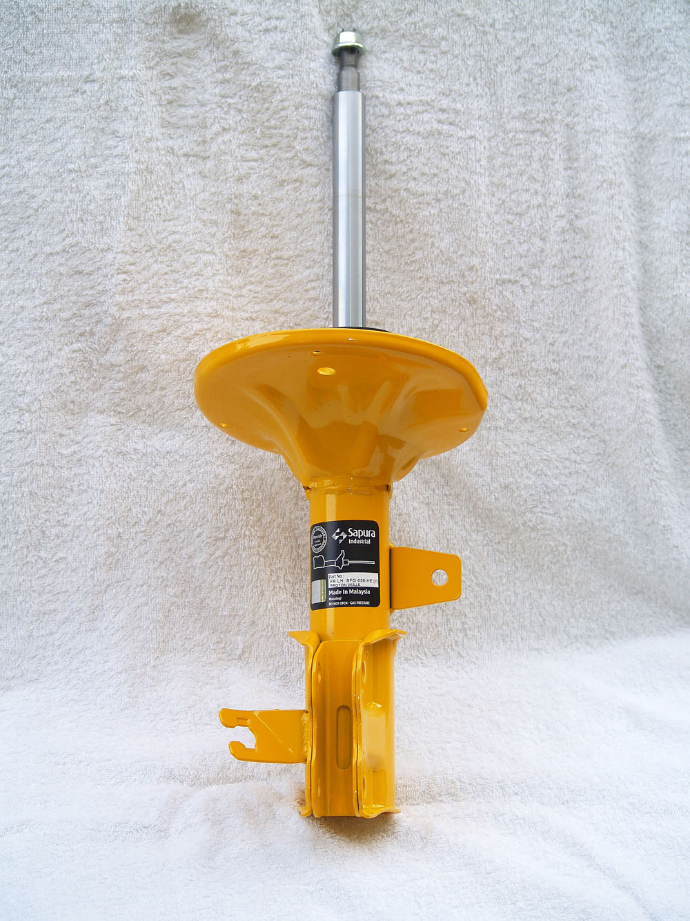
The purpose of this TSB is to provide a quick reference to assist in making easy judgements regarding shock absorber and strut replacements.
Applicable Vehicles: 2006 – 2007 model year Toyota vehicles.
Condition: Slight oil seepage from oil seal case
Action: Normal oil evaporation — NOT necessary to replace the shock absorber
Condition: Moderate oil seepage from oil seal case
Action: Normal oil evaporation — NOT necessary to replace the shock absorber
BMW Group Recycling Concept Manuals

Sustainability ensured by the ecologically responsible use of resources and materials has been the fundamental policy of the BMW Group for many years. Long before lawmakers introduced appropriate legislation, the BMW Group had developed exemplary processes and methods for the sensible use, recycling and disposal of materials as part of a comprehensive recycling concept.
Sustainability has been a firm element of the BMW Group’s corporate philosophy for many years and is one of the Group’s overriding corporate objectives. This consistent orientation has been duly recognised and acknowledged worldwide: Ever since the introduction of the Dow Jones Sustainability Group Index in 1999 as the world’s most significant stock index for companies pursuing a process of sustained management, the BMW Group has been the leading company in the automotive industry ranking No 1 each year. This recognition of BMW’s sustainability strategy by the financial world is reflected within the Company inter alia by a thorough and comprehensive recycling policy.
The BMW Group not only promotes the efficient use of resources within the entire production process as well as the efficient recycling of end-of-life vehicles in accordance with environmental requirements, but also leads the way in recycling-oriented product design. Such “design for recycling” is indeed one of the three interacting core elements underlying the BMW Group’s recycling strategy. The other two core elements are the designation of materials and the Recycling and Dismantling Centre (RDC) in Lohhof near Munich, which is being upgraded to the status of a fully-fledged competence centre and technology forum for all questions of vehicle recycling.
…
The BMW Group follows a clearly specified procedure in designing parts and components for recycling. To meet recycling standards to the best possible extent from the very beginning in the design phase, recycling specialists first determine the demands made of the components involved. Then, cooperating with construction engineers, they develop solutions within a team. This partnership of interdisciplinary development continues throughout the entire process of product creation, that is from the first concept for a new model all the way to production standard. Benchmarks achieved in the process such as the time required for dismantling or the accessibility of components are revised time and again as work progresses.